Rocky Lou,
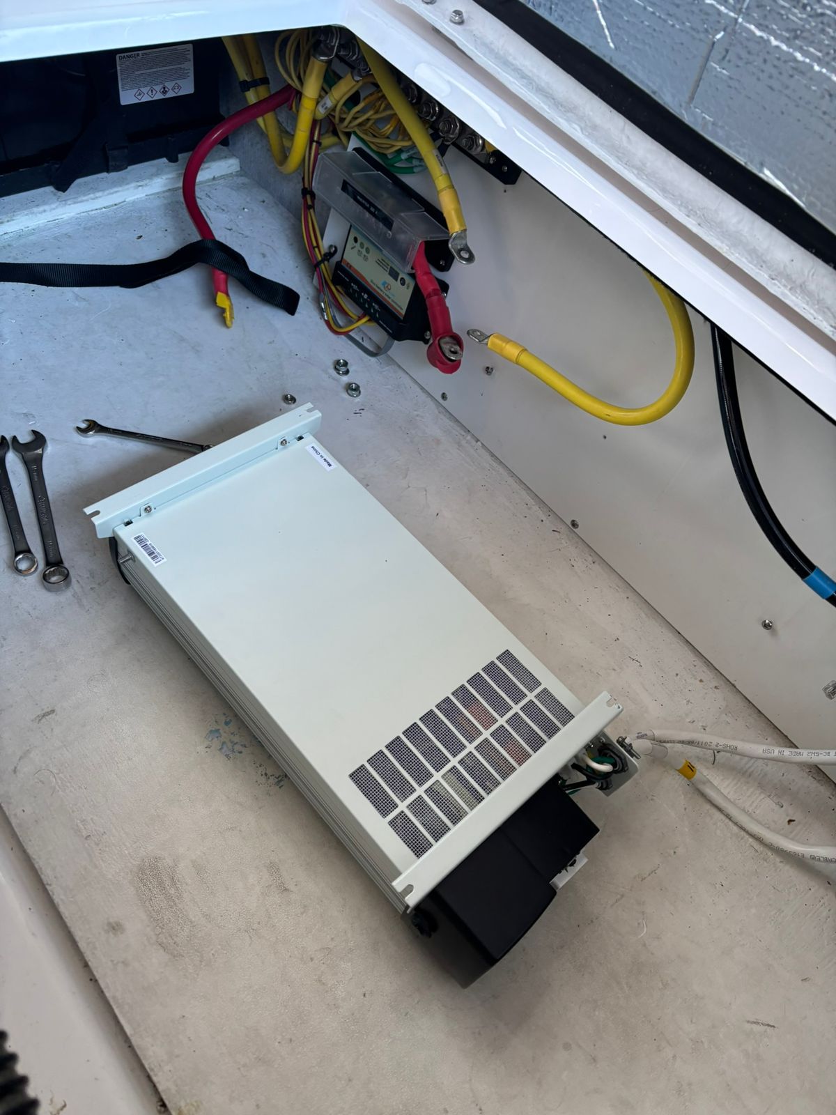
Did you ever find out if the Kisae inverter-charger has a AC output bypass setting? Ours apparently just bit the dust like many others (permanent "r2.0" error message, and no AC power to left side of AC panel [AC outlets, microwave, etc.]). Just trying to see if there's a way to get the AC outlets operating so I can run the air dryers until I can get the Kisae replaced. The Kisae manual does say, "The unit is fully automatic. When utility power is available, the unit is running in AC bypass mode. AC output is supplied from the utility." I have 120 VAC on the AC panel gauge, but no power to the GFCI outlets (galley, mid-berth, v-berth). The water heater breaker is the only AC breaker that seems to work.
Hi Morelord,
Ricardo gave me an extra good deal on a replacement and, thankfully, I'm now accustomed to changing them, it's my third. Here is his reply on bypass, hope it helps, but, in my case seems to complicate matters:
Hello Paul,
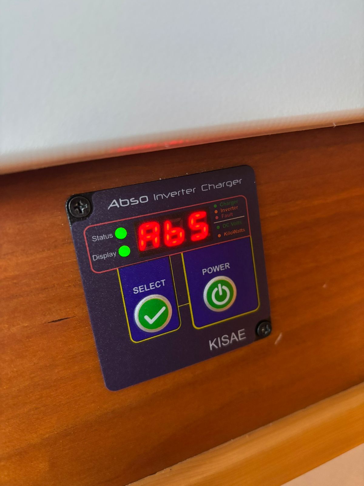
To work in Bypass mode just feed its AC-Input port with 120Vac shore power and wait for about 20 seconds for its built-in transfer switch and charger to start working and so with its Status LED indicator (on the display panel) to pass from flashing amber color (i.e. after connecting the shore power) to solid green.
Try to do it with no AC loads connected /turned-on to its hardwired AC-Output ports, or plugged into its GFCI outlet on the front, to reduce the chance for the E03.
Check the AC-Input port voltage and contact conditions as follows, despite they do not have to do directly with the E03 error:
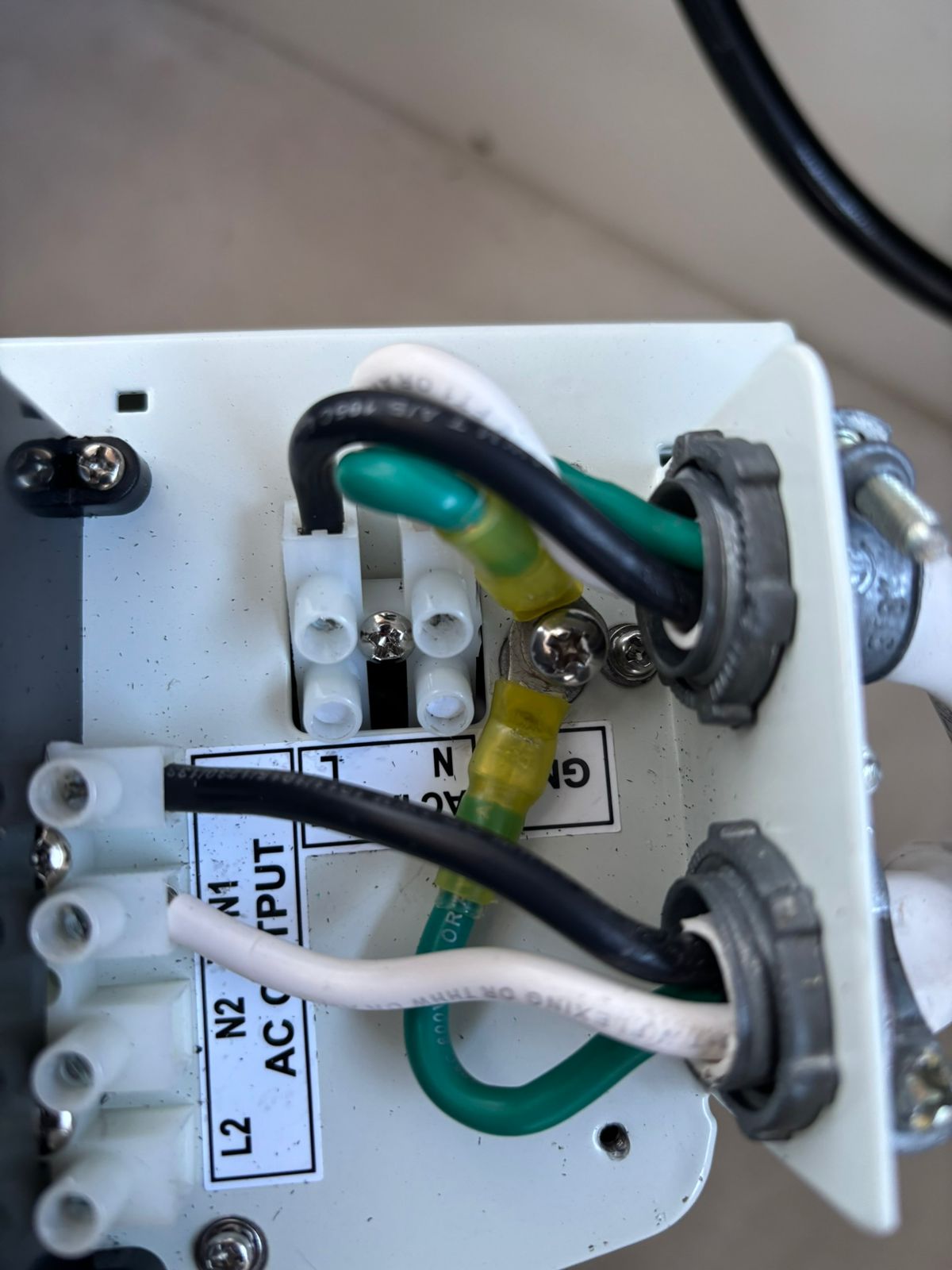
- Make sure the shore power voltage is within the 107 – 129Vac range measured with a digital multimeter right at the Neutral and Line (Hot) bolts of the AC-Input port terminals in the wiring compartment as shown below, especially when using a gas generator rather than utility/hydro AC power. --> Having more than 129Vac at the AC-Input port, even before, may result in a Bypass block condition allowing it to work only in Inverter (Battery) mode, with a subsequent shutdown after disconnecting/shutting-down the shore power, something that we call “Forced Backup” as explained in the attachment. However, this “Forced Backup” does not have to do with the E03 error.
- Check for a possible loose or open contact in the bolt terminals at the AC-Input Neutral “N” and/or Hot “L” connector in the wiring compartment.
With the shore power disconnected and the unit turned off, get access to the wiring compartment and move /pull the edge of the Neutral “N” and Hot (Line) “L” wires to make sure they are not loose. --> Having the bolt of the terminals tightened does
not necessarily mean the wires are so. Make sure the edges of the wires are
below the bolt terminal metal tongue /fin, otherwise, they will remain loose. If necessary, use a thin screwdriver, tweezers, a piece of wire, etc. to pull that metal tongue /fin up to keep it touching the bottom of the fully opened terminal bolt to keep the wire entrances fully opened up to its very end.
Check the AC-Output terminals (if used) the same way.
We suggest crimping pin (or spade) Faston™-type terminals for the AC connections. See more details
after my signature below.
Then, after reconnecting/turning-on the shore power, make sure there is 120Vac nominal measured right at the top of the bolt terminals.
I hope this helps.
Best regards,
Ricardo Torassa
Technical Support Specialist
Kisae Technology Co., Limited
www.kisaepower.com
ricardo.kisae@gmail.com
+1-604-630-8680 (Ext. 506)
+1-877-897-5778 (direct)
Regarding the AC wires and terminals:
For the AC-Grounds (both AC-Input and AC-Output hardwired ones) use a yellow Faston type ring or fork crimped terminals to connect to the unique metal chassis Phillips bolt on the left side of the AC-Input terminals. The color indicates the AWG gauge range being yellow the proper one for AWG # 12/10 wires with an external 20A/30A branch circuit breaker respectively. For AWG #14 gauge and 15A external branch circuit breaker use the blue ones.
For the N and L (Neutral and Line = Hot)”: It uses hardwired screw terminals inside its wiring compartment for the AC-Input and AC-Output connections. Make sure the metal tongues (fins) inside the screw terminal connectors do not remain bent down after counter clocking enough its screw, so blocking the insertion of the wire into it. Check it and if necessary push it up with a small (thin) screwdriver.
Thanks to that tongue, you can insert the bare end of stranded wires directly into the screw terminal connectors without damaging their thin strands when tightening the screw.
However, we also suggest (not mandatory) using a spade or pin yellow Faston-type crimped terminals to the bare end of the stranded wires, as shown below.
IMPORTANT: The screw terminals have a little metal tongue (fin) inside to protect the bare ends of the wires (or their terminals) when the screws of the connector are tightened.
We suggest (not mandatory) using a spade or pin-crimped terminal (as shown below) other than the bare end of the wire.
Then, you have to make sure to insert the pin of the terminal below the tongue inside the screw connector already almost fully unscrewed (at both AC-Input and AC-Output connectors). If necessary and in case the tongue (fin) is bonded down blocking the insertion of the wire (or wire + terminal), you have to use a small screwdriver or sharp object to bond it up and clear the hole.