2008 R-25 Anchor Light and Horn Inoperable

zzr7ky

Member
Joined
Sep 4, 2024
Messages
22
Fluid Motion Model
R-21 EC
Hull Identification Number
FMLT2113H213
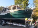
New to me R-25. 100hrs on engine. Sat in indoor rack storage most of the time.
Anchor Light, and Horns Inop.
I replaced the Anchor Light housing, measured continuity.
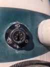
The aged 4 pin connector at the Stack Housing measures 2.7v DC...

So i am looking for any wisdom regarding the wiring route, Ground path, or connector wisdom.

I have read the horn threads. Will attempt separately.
Thanks
 

Attachments

  • 1000003822.jpg
    1000003822.jpg
    1.1 MB · Views: 20
  • 1000003818.jpg
    1000003818.jpg
    2.1 MB · Views: 20
This is the 4-pin connector installed on my 2012 R27. It looks very similar to yours.

 
That's it! Thanks.
Still only have 2.8v at the connection... I need to winterize before I chase this down.
 
Low voltage with no current flow usually indicates a bad ground. The wiring is spliced under the stack then runs down behind the spice rack on starboard side of cabin then to the panel switch at helm. If you don't have the wiring schematics you should be able to find them here on the site. If not PM me and I'll send them when I get home in a couple of weeks.
 
I had a bad pin connection when I bought our boat. I couldn't find the replacement 4-pin connector like the one posted above, so I just spliced the wires back and installed a waterproof clamshell type fitting for the wire run. Low voltage does not necessarily mean a bad ground, it means one of the two DC power supply wires, either the positive or the negative has a bad connection. Likely on that pin connector where they're soldered to the pins (that's where mine was broken).
I never did figure out how the anchor light was switched, and the spotlight was operated both up/down and left/right with just 4 wires. Two are for DC + and DC -, the other two somehow manage every thing else.
 
……spliced the wires back and installed a waterproof clamshell type fitting for the wire run…….
I would not recommend replacing that 4-pin connector with a permanent clamshell connection on boats where the folding mast utility is going to used. On my 2012 R27, the mast folds forward. There is not enough slack in the wiring from the connector to the mast to fold it so the connector needs to be unscrewed and separated before folding the mast. The cable to the radar does use a clamshell because a pinned connector can’t be used. There is enough slack in that cable to fold the mast. Just a heads-up.
 
Last edited:
I would not recommend replacing that 4-pin connector with a permanent clamshell connection on boats where the folding mast utility is going to used. On my 2012 R27, the mast folds forward. There is not enough slack in the wiring from the connector to the mast to fold it so the connector needs to be unscrewed and separated before folding the mast. The cable to the radar does use a clamshell because a pinned connector can’t be used. There is enough slack in that cable to fold the mast. Just a heads-up.
I have no trouble folding my mast with the clam shell instead of the pin connector, there is plenty of slack in the wire.
 
I have no trouble folding my mast with the clam shell instead of the pin connector, there is plenty of slack in the wire.
There’s no question some boats do have enough slack, but there are boats out there that do not have plenty of slack. Mine is one and there are likely others.

There is a reason the factory did not use a clamshell for that wiring— to facilitate removal of the mast. I have had to remove my mast a couple of times. With the mast wires secured by a clamshell, to remove the mast, the wires to the mast light will have to be either cut or disconnected from the light fixture and pulled down the mast center tube. The 4-pin connector eliminates that problem.
 
Assuming you have measured no voltage at the light and horn?

Verify the fuse is good for the horn and light then.

Start at the switch, with the DC power off, pull the switch panel, you will need to run a jumper from a negative connection for this. Turn the DC power back on, and test at the switch for VDC, and with your multimeter connected to the negative jumper, and the switch off, check for VDC at the switch (not sure what terminal). Turn the switch on and check for a second terminal with VDC. This will tell you if you have a defective switch.
 
Back
Top